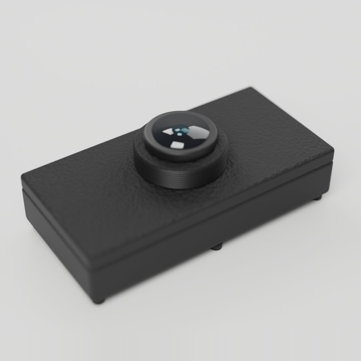
Camera
HD camera module for image capture and vision projects
OV5640 camera with its own on-module co-processor. It captures and JPEG-encodes on board, then hands the compressed frames to the motherboard over SPI, so no image processing happens on the ESP32. Ideal for vision, monitoring, and time-lapse projects.
For ages 14 and up. Not a toy. Contains small parts: choking hazard. Keep away from children under 3. Adult supervision recommended.
Made by Atech ApS, Lille Strandstræde 6A, st. th., 1254 København K, Denmark.
Technical specifications
- Part
- OV5640 Camera (SPI)
- Interface
- Digital
- Ports
- 2 neighbouring ports
- Current
- ~250 mA
- Size
- 39.5 x 19.7 x 14.4 mm
Pins
- 3.3V (first port)
- supply
- GND (first port)
- ground
- Data A (first port)
- MISO: module to board
- Data B (first port)
- MOSI: board to module
- 3.3V (second port)
- supply
- GND (second port)
- ground
- Data A (second port)
- SCLK: serial clock
- Data B (second port)
- CS: chip select
Key features
- OV5640 sensor, 160x120 up to 1280x720
- On-module JPEG encoding, frames arrive ready to display
- Still image and live video capture
- Adjustable resolution and quality
Common applications
Technical
Camera
OV5640 Camera (SPI)
OV5640 image sensor with its own ESP32-S3 co-processor. The module captures and JPEG-encodes on board, then hands the compressed bytes to the motherboard over a 4-wire SPI link: MISO on Line A1, MOSI on Line B1, SCLK on Line A2, CS on Line B2. 160x120 up to 1280x720. Double module spanning two adjacent ports. 3.3 V only.
capture_frameCapture one JPEG frame into the driver's bufferstreamStart or stop continuous capture, so frames are always freshset_resolutionSet capture resolution, QQVGA through HDset_qualitySet JPEG quality, 0-63, lower is bettercamera_statusReport link and sensor state
CAMERA (OV5640 + on-module co-processor, SPI):
- A FRAME IS ALREADY A JPEG. capture() fills the driver's buffer; frameData() and
  frameLength() are the compressed bytes, valid until the next capture(). There are no
  pixels to convert and no sensor registers to poke.
- capture() BLOCKS: roughly 60-120 ms at VGA, longer at higher resolutions. Drive it from
  a button, a timer or its own task, never a tight loop path.
- startStream() does not push frames at you: it keeps a fresh frame held on the module so
  capture() skips the exposure wait. stopStream() afterwards saves power.
- setResolution() takes ATECH_CAM_RES_QQVGA, _QVGA, _VGA, _SVGA, _XGA or _HD, never a string.
- setQuality() is the SENSOR's scale: 0-63, LOWER IS BETTER, default 12. 90 is the worst.
- begin() returns false when the module does not answer; that is not fatal. Keep running
  and offer reconnect(). statusText() == "no_sensor" means the module answers but its
  sensor did not start, almost always an unseated ribbon the user can fix.
- retryCount() should stay near zero; a climbing count means a marginal connection.
- The camera needs a HARDWARE SPI host (the chip has two). With the camera, a microSD
  card and a screen on one board, call atech::reserveSpiHosts(n) first in setup(),
  before any begin(), with n = the number of cameras + microSD cards, so the screen
  bit-bangs instead of taking a host the camera needs (atech_spi_hosts.h). Do not call
  setSpiHost(); begin() claims a free host itself.
- Show frames on a screen or save them to a microSD card. Studio's firmware transport
  does not carry images to the app.
A Capture button and a stream toggle, a resolution dropdown (QQVGA through HD) and a quality slider, with a status line showing the camera state, the last frame's size and the capture time. Frames are shown on a screen module or saved to a microSD card on the board.
| Pin | Line | Dir | Function |
|---|---|---|---|
| 1 | HV | – | not connected |
| 2 | 5V | – | not connected |
| 3 | 3.3V | input | supply |
| 4 | GND | – | ground |
| 5 | Data A | **output** | MISO: module to board |
| 6 | Data B | input | MOSI: board to module |
| Pin | Line | Dir | Function |
|---|---|---|---|
| 7 | HV | – | not connected |
| 8 | 5V | – | not connected |
| 9 | 3.3V | input | supply |
| 10 | GND | – | ground |
| 11 | Data A | input | SCLK: serial clock |
| 12 | Data B | input | CS: chip select |
from p2p/ground_truth/hardware/prototyping_line/modules/camera.md
The doc for this module names no separate part. It is passive or discrete hardware, so there is no chip datasheet to read.